
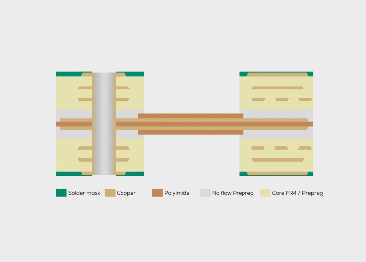
A rigid-flex printed circuit board—also known as a rigid-flex PCB—consists of rigid sections and integrated flexible sections. The flexible sections provide the electrical connection between multiple rigid sections of the assembly and allow for defined bends within the final product.
Rigid-flex printed circuit boards are particularly well-suited when multiple printed circuit boards need to be electrically connected in different mounting orientations. Unlike separate printed circuit boards connected via connectors, cables, or solder joints, this approach provides an integrated, easy-to-install, and reliable overall solution.
KSG manufactures Rigid-flex printed circuit boards at our own production facilities in Europe – in Germany and Austria. As an experienced printed circuit board manufacturer, KSG supports customers from the initial design concept through layer layout to mass production.
Early coordination is crucial, especially for rigid-flex printed circuit boards: Material selection, layer structure, bending radius, transition zones, contour machining, and mechanical stress relief have a significant impact on the assembly's long-term reliability.
Rigid-flex printed circuit boards replace cables, connectors, and additional solder joints. This reduces the number of potential sources of error in the assembly.
Flexible circuit board sections allow rigid assembly layers to be connected to one another in three dimensions. This enables compact, lightweight, and functionally integrated electronic designs.
Since several PCB sections are already integrated into the PCB assembly, the effort required for component placement, assembly, testing, and logistics is reduced.
The integrated design reduces manual processing steps and minimizes the risk of assembly errors, contact issues, or wiring errors.
Rigid-flex printed circuit boards are suitable for applications with high requirements for reliability, mechanical stability, and traceability—such as in aerospace, defense, medical technology, industrial electronics, and the automotive industry.
For rigid-flex transitions subject to particularly high stress, KSG offers additional edge sealing or mechanical stress relief through dispensed filling systems.
The transitions between rigid and flexible sections of a rigid-flex printed circuit board are among the most mechanically sensitive areas of the board. This is where different material thicknesses, stiffness levels, and stress zones meet. Targeted edge sealing can help to further stabilize these transition areas.
KSG offers the Dispensing from Filling Systems in Rigid-Flex Transition Areas . The applied material acts as a mechanical stress reliever and protects the transition zone from localized stress peaks.
This additional technology is particularly relevant for applications with high reliability requirements, such as in:
Production is tailored to each specific project based on the drawings and depends on the respective PCB design. KSG assists you as early as the development phase in determining whether edge sealing is appropriate for your application.
The manufacturing process for rigid-flex printed circuit boards is based on the combination of different types of materials. First, the rigid FR4 cores are manufactured in the same way as multilayer printed circuit boards. At the same time, the flexible conductor layers based on polyimide are produced.
The rigid and flexible semi-finished products are then bonded together in a dedicated pressing process. Low-flow or no-flow prepregs are used for this purpose. Before the pressing process, these composite materials are structured in such a way that the areas intended to be flexible remain free and are not bonded to the rigid areas.
In subsequent processing, the transitions between rigid and flexible areas are contoured. This involves removing excess rigid material from the flexible zones. The result is defined flexible areas with the intended bending and installation properties.
Suitable for simple flexible connections with a flexible section on one side and an asymmetrical overall design.
For applications with higher wiring density in the flexible section and asymmetrical material distribution.
For particularly well-balanced mechanical properties and defined bending ranges.
| Parameters | Specification | Note |
|---|---|---|
|
Materials |
Polyimide / FR4 |
Combination of flexible and rigid materials |
|
Number of layers |
2–18 |
depending on the configuration |
|
End copper |
0.6–3.2 mm |
Final thickness depends on the rigid region |
|
Ladder structures |
depending on the terminal copper and the design |
|
|
Smallest drill diameter |
0.20 mm |
technologically dependent |
|
Aspect ratio through hole |
≤ 1:10 |
— |
|
Bending radius |
≥ 1 mm |
depending on the structure and flexible layers |
|
Bending angle |
≤ 180° |
for static bending stress |
|
Solder Mask & Surfaces |
ENIG, chem. tin, OSP, electroplated Ni/Au |
no HAL |
|
Contour production |
Milling, Scoring, Support Brides, Laser Cutting |
depending on the geometry |
|
Contour production |
optional |
Filling Systems for Rigid-Flex Transitions |
Rigid-flex printed circuit boards are used wherever electronic assemblies need to be integrated in three dimensions in a compact, lightweight, and reliable manner.
Compact control units, sensors, camera systems, and applications with a high degree of integration.
Control systems, sensors, measurement systems, and embedded systems with complex installation spaces and high reliability requirements.
Compact electronics for imaging systems, portable medical devices, and miniaturized assemblies.
Safety-critical applications in which mechanical strength, functional safety, and consistent quality are crucial.
Avionics, satellites, sensors. Highest reliability requirements, qualified processes
Flexible connections for three-dimensional sensor arrays, compact measurement modules, and installations with minimal movement.
| Criterion | Rigid-flex printed circuit board | Semi-flexible printed circuit boards | HSMtec® 3D |
|---|---|---|---|
|
Basic Principle |
Combination of rigid FR4 sections and flexible polyimide layers |
Deep-milled FR4 printed circuit board with a defined bending area |
FR4 printed circuit board with integrated copper profiles and 3D bending capability |
|
Suitable for |
Complex 3D structures with high reliability |
Simple 3D Structures with a Focus on Cost-Effectiveness |
Self-supporting 3D structures with high-current or thermal management |
|
Bending Angles // Bending Radii |
≤ 180° // ≥ 1 mm |
≤ 180° // ≥ 5 mm |
≤ 90° |
|
Multiple bends |
✓ Very well suited |
~ Limited suitability |
✗ Designed for a single bend only |
|
UL-certifiable |
✓ Yes |
✓ Yes |
✓ Yes |
|
HDI-compatible |
✓ Yes |
✓ Yes |
✓ Yes |
|
Self-supporting |
✗ No |
✗ No |
✓ Yes |
|
Impedance controlled via bends |
✓ Suitable |
✓ Suitable |
✗ Not suitable |
Semi-flexible printed circuit boards consist primarily of rigid base material and can be bent to a limited extent. Rigid-flex printed circuit boards combine rigid FR4 sections with integrated flexible sections. This allows multiple rigid assembly sections to be connected in three dimensions.
Rigid-flex is a good choice when the goal is to reduce installation space, minimize assembly effort, and increase reliability. Since connectors, cables, and additional solder joints can be eliminated, the number of potential sources of error is reduced.
In edge sealing, a suitable filling material is precisely applied to the transition area between the rigid and flexible sections of the printed circuit board. This application serves as mechanical stress relief and can provide additional protection for sensitive transitions.
Edge sealing is particularly important in safety-critical applications, such as in aerospace, defense, medical technology, and industrial electronics. It can also be beneficial for assemblies subject to high mechanical stress, vibrations, or demanding assembly conditions.
Depending on the requirements, products such as LOCTITE Ablestik 45 Clear or Scotch-Weld 2216 B/A can be used. The specific material selection is determined on a project-by-project basis.

"Talk to us in the early stages of development. Together we will find the solution that will make your product even better."
Technical Support, KSG Group
The Technical support from KSG supports your rigid-flex PCB from the initial design concept through to mass production. Our services include: PCB design and layout review, impedance calculation, layer stackup design using rigid and flexible layers, as well as long-term and aging tests.
In the Digital Design Compass all design rules, assembly variants and design-to-cost notes for all KSG technologies are available digitally around the clock - free of charge for registered users.
Tell us about your requirements. Our team of experts will get back to you within one working day.

Talk to us in the early development phases of your project and contact our team of experts. Together we will find the solution that will make your product even better.

From design and layout checks to various calculations and thermal analyses - the experienced, competent Technical Support team will be happy to help you.
You are currently viewing placeholder content from Vimeo. To access the actual content, click the button below. Please note that doing so will result in data being shared with third-party providers.
More InformationYou are currently viewing placeholder content from YouTube. To access the actual content, click the button below. Please note that doing so will result in data being shared with third-party providers.
More InformationYou need to load content from reCAPTCHA to submit the form. Please note that doing so will result in your data being shared with third-party providers.
More InformationYou are currently viewing placeholder content from Vimeo. To access the actual content, click the button below. Please note that doing so will result in data being shared with third-party providers.
More InformationYou are currently viewing placeholder content from YouTube. To access the actual content, click the button below. Please note that doing so will result in data being shared with third-party providers.
More InformationYou are currently viewing placeholder content from Bunny Stream. To access the actual content, click the button below. Please note that doing so will result in data being shared with third-party providers.
More InformationYou are currently viewing placeholder content from Wistia. To access the actual content, click the button below. Please note that doing so will result in data being shared with third-party providers.
More InformationYou are currently viewing placeholder content from Facebook. To access the actual content, click the button below. Please note that doing so will result in data being shared with third-party providers.
More InformationYou need to load content from hCaptcha to submit the form. Please note that doing so will result in your data being shared with third-party providers.
More InformationYou need to load content from reCAPTCHA to submit the form. Please note that doing so will result in your data being shared with third-party providers.
More InformationYou need to load content from reCAPTCHA to submit the form. Please note that doing so will result in your data being shared with third-party providers.
More InformationYou need to load content from reCAPTCHA to submit the form. Please note that doing so will result in your data being shared with third-party providers.
More InformationYou need to load content from turnstile to submit the form. Please note that doing so will result in your data being shared with third-party providers.
More InformationYou are currently viewing placeholder content from Instagram. To access the actual content, click the button below. Please note that doing so will result in data being shared with third-party providers.
More InformationYou are currently viewing placeholder content from reCAPTCHA. To access the actual content, click the button below. Please note that doing so will result in data being shared with third-party providers.
More InformationYou are currently viewing placeholder content from X. To access the actual content, click the button below. Please note that doing so will result in data being shared with third-party providers.
More Information